orca-robotics
INTRODUCTION
Overview
Download and Install
Quick Start
Documentation
Publications
REPOSITORY
Interfaces
Components
Libraries
Utilities
Software Map
DEVELOPER
Tutorials
Examples
Dev Guide
Dashboard
Wiki
login/pass: orca/orca
PEOPLE
Contributors
Users
Project
Download
Mailing lists
Laser2d
[Components, Stand-Alone Components, IceBox Services, C++, Linux, QNX, Windows]
A hardware abstraction component for scanning laser range-finders.
More...- Provides
- Home
- LaserScanner2d [Laser2d.Provides.LaserScanner2d]
- Status
- Requires
- none

- Drivers
- Operation
- Configuration
Laser2d.Config.DriverLib(string)- Name of shared library containing the hardware driver
- Valid values are at least: { 'libHydroLaserScanner2dSickAcfr.so', 'libHydroLaserScanner2dSickCarmen.so', 'libHydroLaserScanner2dPlayerClient.so', 'libHydroLaserScanner2dFake.so' }
- Default: "libHydroLaserScanner2dSickCarmen.so"
Laser Settings
Laser2d.Config.MinRange(double) [m]- Valid Values: MinRange>=0.0
- Default: 0.0
Laser2d.Config.MaxRange(double) [m]- Valid Values: MaxRange>0.0
- Default: 80.0
Laser2d.Config.FieldOfView(double) [deg]- Valid Values: 0.0<FieldOfView<=360.0
- Default: 180.0
Laser2d.Config.StartAngle(double) [deg]- Valid Values: -360.0<StartAngle<=360.0
- Default: -FieldOfView/2.0
Laser2d.Config.NumberOfSamples(int)- Number of range samples in a single scan.
- Valid Values: NumberOfSamples>0
- Default: 181
Geometry
Laser2d.Config.Offset(Frame3d) [m, deg]- Position of the laser with respect to the robot's local coordinate system.
- Format: x y z roll pitch yaw (space separated)
- Example: a laser mounted upside down with now translation: "0.0 0.0 0.0 180.0 0.0 0.0"
- Default: 0.0 0.0 0.0 0.0 0.0 0.0
Laser2d.Config.AllowRollCompensation(bool)- If TRUE and the roll in laser offset is exactly 180.0 degrees (with no pitch), then the scan is flipped left-to-right internally and the reported roll angle is 0.0 degrees. If FALSE, the scan and the offset are left unmodified.
- Default: 1
- Example: The laser is mounted horizontally and upside-down. You want Laser2d to take care of it and not to worry about rotations on the client side. Set the roll angle in
Offsetto 180.0 and setAllowRollCompensation=1. As a result, the laser will appear to be mounted normally (top-side-up) to all clients.
Laser2d.Config.Size(Size3d) [m,m,m]- Physical dimensions of the laser device.
- Format: length width height (space separated)
- Default: 0.155 0.155 0.185 (SICK LMS dimensions)
- See also:
- Individual drivers may have additional configuration parameters which are specified as Laser2d.Config.XXX. See driver documentation.
Internal Structure

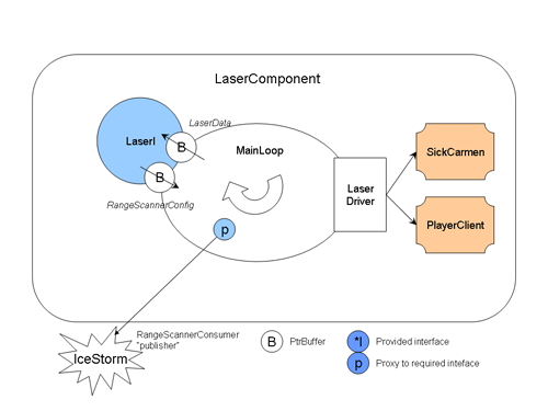
For developers: the code conforms to the basic approach described in the notes on Suggestions on the Internal Component Structure.
How does the Sick Laser work?
Note: This article is adapted from a posting by Brian Gerkey to the Player/Stage users mailing list on 2004-07-22.The mirror in the laser rotates at 75 Hz, so that's its "natural" frequency. It can only sample once per degree, which means the laser can generate a 180-degree scan, with resolution of 1 degree, every 1/75th of a second. If you want 0.5 degree resolution, the laser actually takes two scans at 1 degree resolution, with the second scan offset by 0.5 degrees, then interlaces them to produce a single scan with 0.5 degree resolution. This, of course, requires 1/37.5 seconds. If you want 0.25 degree resolution, this interlacing requires 4 scans, which takes 1/18.75 seconds. This mode is further complicated by the fact that there's a limit of 401 readings per scan, so if you want 0.25 degree resolution, you also have to reduce the angular aperture to <= 100 degrees.
So that's how fast the laser can generate scans. How fast can it shove them down the serial line? Much slower than you might think. A 180-degree scan, at 1-degree resolution, is 180 readings, at 2 bytes per reading. That's 360 bytes. Assuming a perfect 38.4kbps line with zero overhead, you can send 360-byte packets at about 13.3Hz (remember that the small "b" in "kbps" means *bits*, not *bytes*):
38400 bps / 8 / 360 = 13.3 packets/sec
In practice, you see a data rate of between 10Hz and 12Hz, depending on the quality of the serial cable. If you want 0.5 degree resolution, then each scan is doubled in size, to around 720 bytes. The data rate is correspondingly halved, so these packets can theoretically be sent over a 38.4kbps line at 6.67Hz. In practice, you see a rate of around 5Hz.
Now, if you have a 500Kbps RS422 line (e.g., using a USB-serial converter), then the serial line is no longer the rate-limiting component. You can get data as fast as the laser generates it. So, in 1-degree mode, you'll get scans at 75Hz. In 0.5-degree mode, you'll get them 37.5Hz. And so on.
Notes
Only the fake driver will build for Windows.
- Authors

 1.4.5
1.4.5