INTRODUCTION
Overview
Download and Install
Quick Start
Documentation
Publications
NONFRAMEWORK CODE
Driver Interfaces
Drivers
Libraries
Utilities
FRAMEWORK CODE
Interfaces
Components
Libraries
Utilities
Full Software Listings
DEVELOPER
Tutorials
Examples
Dev Guide
Dashboard
PEOPLE
Contributors
Users
Project
Download
Mailing lists
OrcaView2d
[Utilities, Stand-Alone Components, C++, Linux]
Graphical display of global and local 2D information. More...
Graphical display of global and local 2D information.
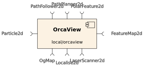
- Provides
- orca_interface_home
- Requires
The way interfaces are configured is different for the GUI. See explanations below.

- Operation
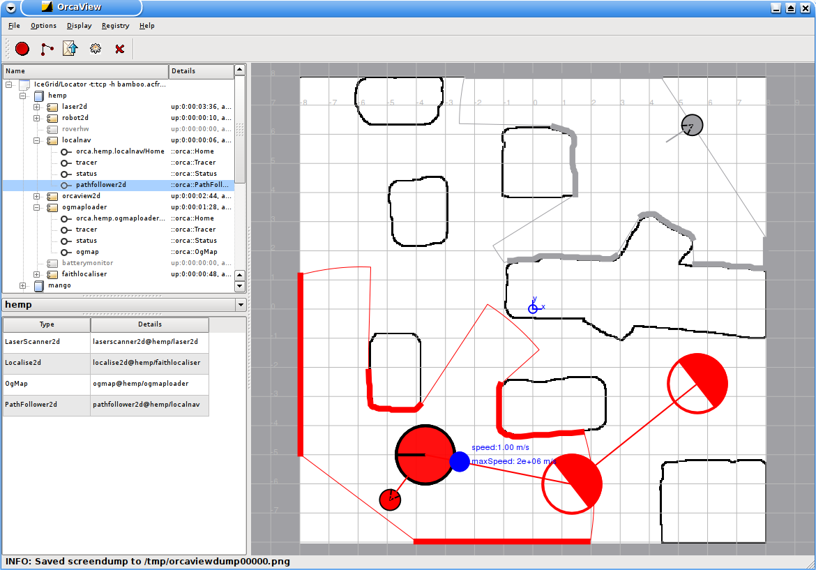
Orcaview consists of three parts: the registry view (upper left), the element view (bottom left), and the world view (right).
- Registry view
- The registry view displays all currently existing "adapters" (interface/platform) in the Orca world by connecting to the central Icegrid registry. Pressing
F5triggers a request to the registry to update the view.
- Element view
- This table lists the GuiElements which are currently setup in the GUI. Each GuiElement has a "type" (e.g. LaserScanner2d) and "uniqueId" (e.g. laserscanner2d/laser2d). A GuiElement typically hooks up to a single required interface but there are other options: no interfaces (e.g. the GridElement), multiple required interfaces (e.g. OgMapsCombinedElement), and provided interfaces (no example in Orca at the moment).
Two mechanisms exist to add GuiElements:
- by specifying them in the
.cfg file (see below) - by interactively adding them using the registry view. Different modes exist:
- Single interface: right-click on an interface and select "Add to project". If the interface is supported, it will be added, otherwise an error message will appear.
- Multiple interfaces: several interfaces can form a single GuiElement (see e.g. OgMapsCombined which subscribes to two occupancy grid map interfaces and displays both of them as one element). Hold down the
CtrlorShiftkey to select multiple interfaces. - All platform interfaces: right-click on a platform or component and select "Add all supported interfaces". It goes through the list and tries to connect all of them. The non-supported ones will trigger error messages in the status bar.
Right-clicking on elements in the elements view brings up configuration/interaction options. GuiElements can also be removed interactively this way.
- World view
- The world view shows the graphical representation of the GuiElements. Each GuiElement is periodically updated, stores its own data, paints itself to the world view, adds buttons to the toolbar and entries to the menu. This modular design makes the GUI extensible ( see Extensibility ).
The world view is usually a global coordinate system but it can also be centered on a particular GUI element (e.g. a local view of a particular platform).
- Plugin libraries
- In order to instantiate GuiElements, OrcaView dynamically loads libraries containing GuiElement factories. See the
Logger.Config.General.FactoryLibNamesconfig parameter for how to add new factories. This plug-in architecture allows custom GuiElements to be added without modifying the main source code.
Multi-robot systems
When many platforms need to be displayed, the element view table grows quickly and you it's hard to figure out which GuiElements belong to which platform. For this situation, it is possible to filter the element view list on a per-platform basis. By selecting a particular platform in the combo box above the list, only elements belonging to that platform will be displayed. At the same time, all GuiElements belonging to that platform are displayed in their respective platform color (assigned at startup). All other GuiElements are grayed out. If everything needs to be displayed, choose the special "global" platform from the list.
A second way of putting a particular platform into focus, is to click on a localised representation of them in the world view (e.g. Localise2d of a robot). The combo box changes simultaneously. By hovering the mouse pointer above localised GuiElements, a tooltip with the platform name shows up. The origin of the world view (indicated by a cross) corresponds to the "global" platform (try clicking on it).
User input
Apart from receiving information from interfaces, users can also send data to them via their corresponding GuiElements. Each element adds its own buttons to the toolbar and entries into the menu. Right-clicking on the elements in the element view brings up some interaction options too.
The following interactions are currently implemented. Note that they work on a per-element basis, i.e. you only interact with a single element:
- PathFollower2d interactions:
- drawing paths (shortcut F10): choose the "Pathfollower waypoints mode" icon. Draw connecting waypoints by left-clicks. They show up as circles with uncertainty in distance (circle diameter) and heading (filled wedge). The default settings for the waypoints can be found at Options->Waypoint Settings. Right-clicking close to the last waypoint removes it. Middle-clicking close to a waypoint lets you change the waypoint parameters. All waypoints can be discarded by clicking the "Discard" icon. When satisfied, click the "Send" icon (shortcut F11) to send it to the interface. A moment later, you should see the path sent back by the interface in the platform's color.
- activate path (shortcut F12): After sending a new path, clicking on the "Go robot" icon will activate the path.
- stopping robot (shortcut ESC): clicking on the "Stop robot" icon will send an empty path to the pathfollower which stops the robot.
- Open/save pathfollower waypoints: once subscribed to a orca_interface_pathfollower2d interface, you can save the displayed path to a text file (could be the one you just sent to it). You can load the path back into the GUI later. It can then be sent to the interface(s) by clicking the "Send" button.
- PathPlanner2d interactions: choose the "Pathplanner waypoints mode" icon. Draw/remove/configure waypoints the same way as described for the PathFollower2d. This defines a "coarse" path which gets sent to the PathPlanner interface for "fine" pathplanning by clicking the "Send" button. If the path is computed successfully, the pathplanner sends back a computed fine-grained path which is displayed differently.
- Save feature map: once subscribed to a orca_interface_featuremap2d interface, you can save the displayed feature map to a text file. It can be loaded later by a component that provides the orca_interface_featuremap2d interface (not the GUI!), e.g. FeatureMapLoader.
- Save OG map: once subscribed to a orca_interface_ogmap interface, you can save the displayed occupancy grid map to different file formats which are determined via the file extension you specify in the dialog. The saved files can be loaded later by the OgMapLoader.
Supported file formats are:
- binary ICE stream file ( extension
.bin ). The advantage is that this file contains all information of the OgMap including origin, resolution etc. - bitmaps: one pixel per cell (extensions: .bmp .jpg .jpeg .png .ppm .xbm .xpm ). The advantage is that these files can be processed.
- Save PixMap: once subscribed to a orca_interface_pixmap interface, you can save the displayed pixmap to different file formats which are determined via the file extension you specify in the dialog. The saved files can be loaded later by the PixMapLoader. Supported file formats are bitmaps (see above).
Sometimes, it is desirable to interact with many elements at the same time, e.g. to stop all robots. These type of interactions are implemented using keyboard shortcuts. Currently, we have:
- Stop for all PathFollower2dElements: ESC
- Go for all PathFollower2dElementss: F12
Screenshot
Here's a screenshot of the GUI connected to a few interfaces belonging to two platforms. Robot "hemp" is in focus and thus its GuiElements are displayed in color: they are Laser, Localise2d, and PathFollower2d. The other platform's GuiElements are grayed out.

Dependencies
- Qt GUI library >= version 4.1
Configuration parameters
- Elements and their interfaces
GuiElements typically connect to a single required interface but can also have none or several. To be able to configure them, they have "Type" and "Description" configuration options. When the GUI starts up, it will setup the elements which handle the network-related stuff like connecting to interfaces.
OrcaView2d.Config.Element.TypeX(string)- GuiElement type
- X is an arbitrary string, e.g. a number
- Supported types are: LaserScanner2d, Localise2d, Particle2d, PolarFeature2d, PathFollower2d, PathPlanner2d, PixMap, FeatureMap2d, OgMap, Wifi, MultiOgMaps
OrcaView2d.Config.Element.DescriptionX(string)- Free-form string which describes the element, it contains information the element may need to do something useful
- X is an arbitrary string, e.g. a number. Corresponds to 'TypeX' (see above).
- Descriptions are dependent on the Type:
- Types with no network connections (e.g. a Grid or background image): Description is arbitrary and optional
- Types with a single required interface (e.g. LaserScanner2d): interface/component
- Types with several required interfaces (e.g. MultiOgMaps): interface1/component1:interface2/component2: ... :interfaceN/componentN Note that you need a colon as a delimiter.
- General Settings
OrcaView2d.Config.General.FactoryLibNames(string)- names of plugin factory libraries
- default: libOrcaQGui2dFactory.so
OrcaView2d.Config.General.DisplayRefreshTime(int) [ms]- refresh time of the display
- default: 200
OrcaView2d.Config.General.DumpPath(string)- directory to dump files
- currently used for two purposes: (1) screen dumps (filename
orcaviewdumpXXXXX.png) (2) paths sent to pathfollower2d interface (filenamepathdumpXXXXX.png) - default: "/tmp"
OrcaView2d.Config.General.Offset(Frame2d) [m,m,deg]- offset of the GUI's origin wrt the (arbitrarily defined) global coordinate system
- format: x y orientation (space separated)
- default: 0.0 0.0 0.0
- Waypoint Settings
These are the default: waypoint settings that can be changed in the menu later. Choose Options->Waypoint Settings.
OrcaView2d.Config.Waypoints.DistanceTolerance(double) [m]- distance tolerance from waypoint before it has been set as reached
- default: 1.0
OrcaView2d.Config.Waypoints.HeadingTolerance(integer) [deg]- heading tolerance from waypoint before it has been set as reached
- default: 45
OrcaView2d.Config.Waypoints.MaxApproachSpeed(double) [m/s]- maximum approach speed to waypoint
- default: 2e6
OrcaView2d.Config.Waypoints.MaxApproachTurnRate(int) [deg/s]- maximum approach turn rate to waypoint
- default: 2000000
OrcaView2d.Config.Waypoints.SpacingProperty(string)- property that determines the time deltas of subsequent waypoints
- Valid values: {'Time','Velocity'}, corresponding values are specified using
SpacingValue(see below) - Time: time deltas are specified directly in sec; Velocity: time deltas are calculated based on a straight-line distance given the velocity
- default: Velocity
OrcaView2d.Config.Waypoints.SpacingValue(double) [s] or [m/s]- value is interpreted according to the setting of
SpacingProperty(see above) - default: 1.0
- value is interpreted according to the setting of
- Teleoperation parameters
These are configuration parameters for the VelocityControl2d element.
OrcaView2d.Config.VelocityControl2d.SpeedIncrement(double) [m/s]- How much the speed will change for each key-press.
- Default: 0.05
OrcaView2d.Config.VelocityControl2d.TurnRateIncrement(double) [deg/s]- How much the turnrate will change for each key-press.
- Default: 2.0
OrcaView2d.Config.VelocityControl2d.MaxSpeed(double) [m/s]- The maximum absolute linear speed which the component will send out
- Default: 1.0
OrcaView2d.Config.VelocityControl2d.MaxTurnRate(double) [deg/s]- The maximum absolute rotational speed which the component will send out
- Default: 40.0
OrcaView2d.Config.VelocityControl2d.RepeatInterval(float) [s]- Time interval before a repeat command is sent in the absence of a new command.
- Default: 0.1
- Valid values:
- t<0: Only new commands are sent
- t=0: Commands are sent as frequently as possible (terribly inefficient)
- t>0: Commands are sent when new ones are entered, or resent after t seconds (useful if "keep alive" heartbeat is needed).
- Screencapture settings
OrcaView2d.Config.ScreenCapture.TopPad(int)- for screen dumps: number of pixels included in the dumps from the widget top (to get window decoration)
- default: 25
OrcaView2d.Config.ScreenCapture.SidePad(int)- for screen dumps: number of pixels included in the dumps from the widget side (to get window decoration)
- default: 2
OrcaView2d.Config.ScreenCapture.BottomPad(int)- for screen dumps: number of pixels included in the dumps from the widget bottom (to get window decoration)
- default: 2
OrcaView2d.Config.ScreenCapture.CaptureTimerInterval(int) [ms]- time interval between screen dumps
- default: 1000
- Specific Gui element configuration
OrcaView2d.Config.PathFollower2d.ActivatePathImmediately(int)- activate path immediately after sending (1) or wait until go button is pressed (0)
- default: 1
An example configuration file is installed into [ORCA-INSTALL-DIR]/share/orca/cfg/ directory.
Extensibility
Orcaview is designed in a modular way to allow easy extensions. There are two options of how to paint items in the GUI:
- by implementing a new orcagui::GuiElement. This is the preferred method to paint data from provided interfaces.
- by using the "special" orca_interface_qgraphics2d interface. This is the preferred method to paint data which doesn't directly belong to an interface (not included in the Slice interface definition) but is useful for debugging purposes etc.
To see how the first option works, check out the orcagui::LaserScanner2dElement. To see how the second option works, check out PathPlanner which can display the skeleton for a grid-potential-based pathplanning algorithm.
Troubleshooting
If there are problems with OrcaView2d, a good place to start looking is the console from which OrcaView2d was launched. It usually outputs a bunch of diagnostic information to stdout when something goes wrong.
Authors
Tobias Kaupp, Alex Brooks, Alex Makarenko

 1.4.5
1.4.5