orca-robotics
INTRODUCTION
Overview
Download and Install
Quick Start
Documentation
Publications
REPOSITORY
Interfaces
Components
Libraries
Utilities
Software Map
DEVELOPER
Tutorials
Examples
Dev Guide
Dashboard
Wiki
login/pass: orca/orca
PEOPLE
Contributors
Users
Project
Download
Mailing lists
Orca Units and Coordinate Systems
- Note:
- Reviewed for release 2.3.0.
Units
- Inter-Component Communication
- Component Configuration
- Component Code
- Display
Coordinate Frames
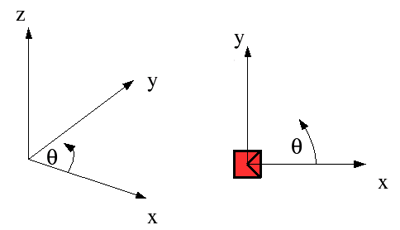
All angles are defined from -pi to pi, NOT 0 to 2pi.
- Inidvidual Coordinate Frames

A global cartesian coordinate frame is shown on the left. Angles are defined anti-clockwise from the x-axis, with zero degrees along the x-axis. The y-axis is at +90 degrees. The z-axis points up.
A local cartesian coordinate frame is shown on the right. The x-axis extends forward from a platform or a sensor, with the y-axis out to the left. The z-axis points up. Zero degrees is directly in front, with angles increasing to the left and decreasing to the right.
- Coordinate Frames in a System

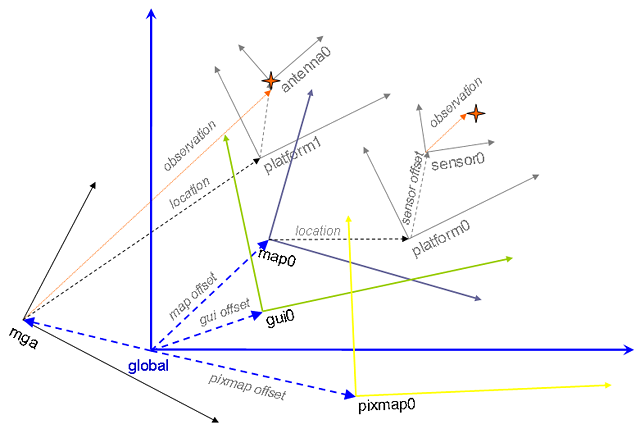
When running a system, one must choose an arbitrary CF to be "global", in a sense that all other ones will refer to it. In practice, it is often convenient to pick one existing CF to be global instead of defining an entirely new one.
Examples of frames:
- a local projection of GPS coordinates, e.g. MGA94 used in Australia.
- a locally-built map, e.g. feature map, occupancy grid map, etc.
- a image of Earth surface.
- GUI frame used to diplay a portion of the environment
The figure above also illustrates two types of robotic sensors:
- sensors which make observations in the sensor CF, e.g. laser scanners, sonars, cameras, inertial measurement units, WiFi receivers, etc., and
- sensors which make observations in non-local CF, e.g. GPS receivers.

 1.4.5
1.4.5